BTClock v4 architecture (UML)
Diagrams render natively on Forgejo via Mermaid. Each section maps to a real subsystem: file paths in the captions are the source of truth — if a diagram drifts from the code, trust the code.
Conventions:
- Class boxes name the C++ class as it appears in source.
- Owns = unique_ptr / optional / by-value member.
- Refs = raw pointer / reference, lifetime managed elsewhere.
- Calls = method invocation, no ownership.
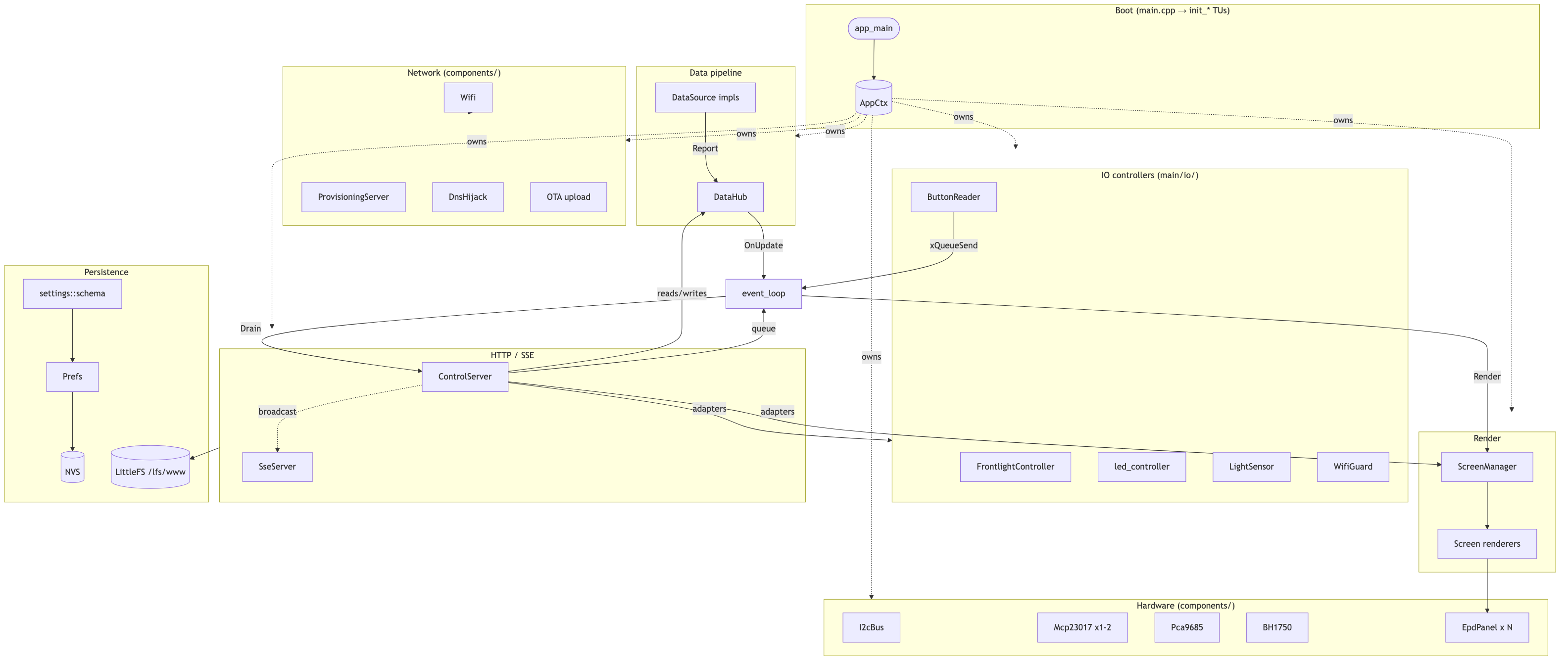
1. Component overview
Top-level subsystems and the wires between them. AppCtx
(main/app/app_ctx.hpp) is the runtime root —
everything else hangs off it.
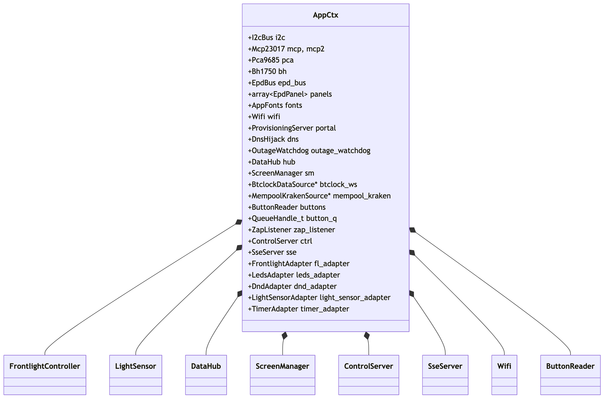
2. AppCtx ownership (class diagram)
AppCtx is behaviour-free — a struct of subsystem handles populated by
the init_* TUs in main/app/boot/. Composition
arrows point from owner to owned.
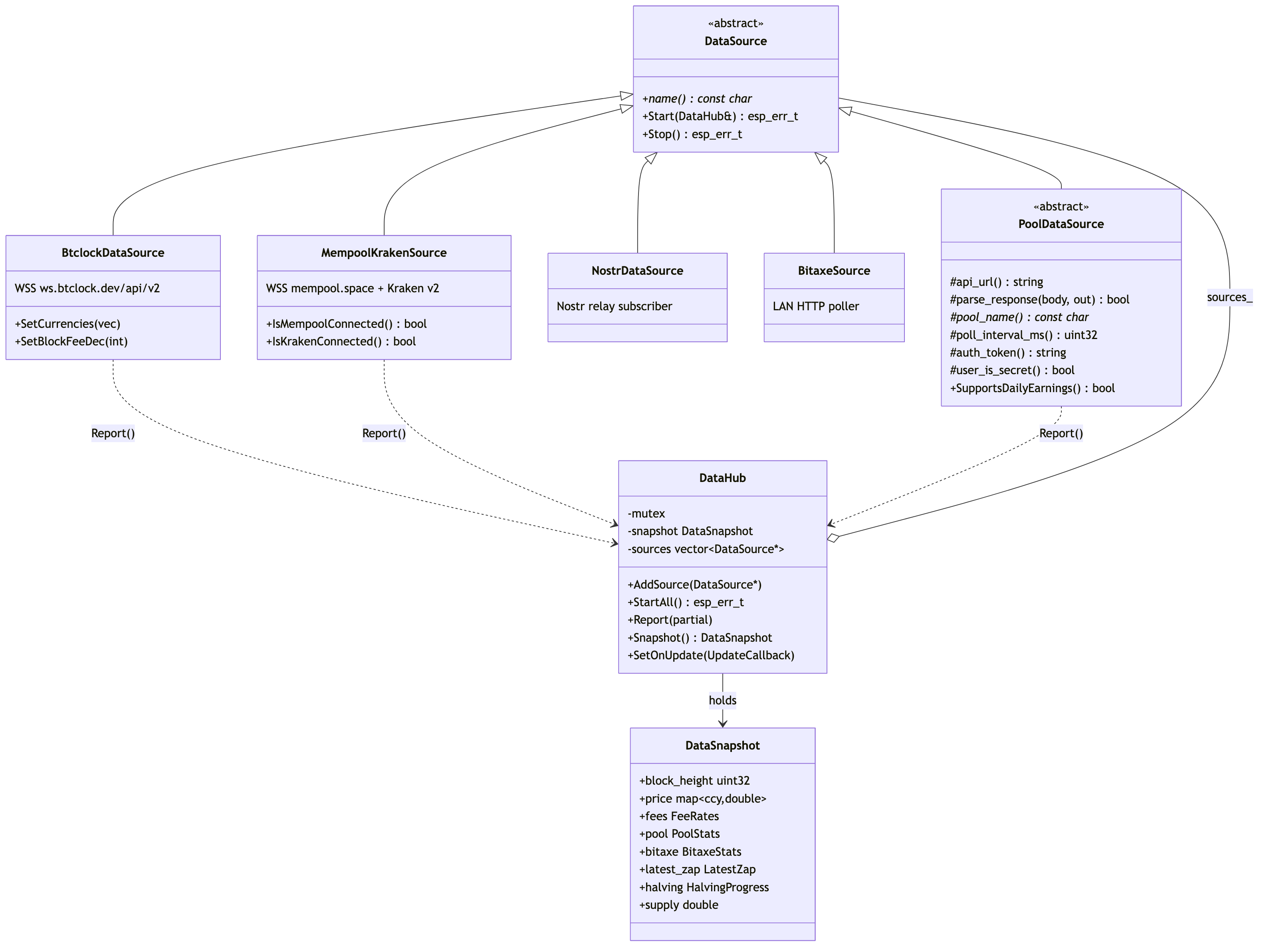
3. Data pipeline (class diagram)
Pure-virtual DataSource
(components/data_core/include/data_core/source.hpp:23)
is the contract; DataHub (hub.hpp)
fan-ins reports under a mutex and fires an UpdateCallback.
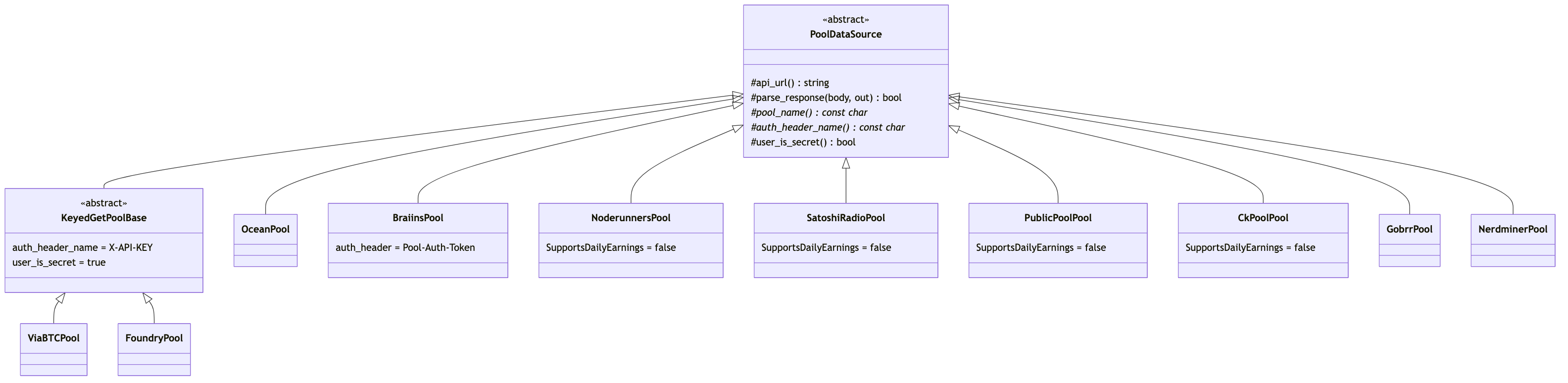
4. Mining-pool plugins (class diagram)
Every mining_pool_* component subclasses PoolDataSource
(components/mining_pool_common/include/mining_pool_common/pool_base.hpp:41).
Two pools (ViaBTC, Foundry) inherit through an intermediate
KeyedGetPoolBase that swaps the auth header to X-API-KEY.
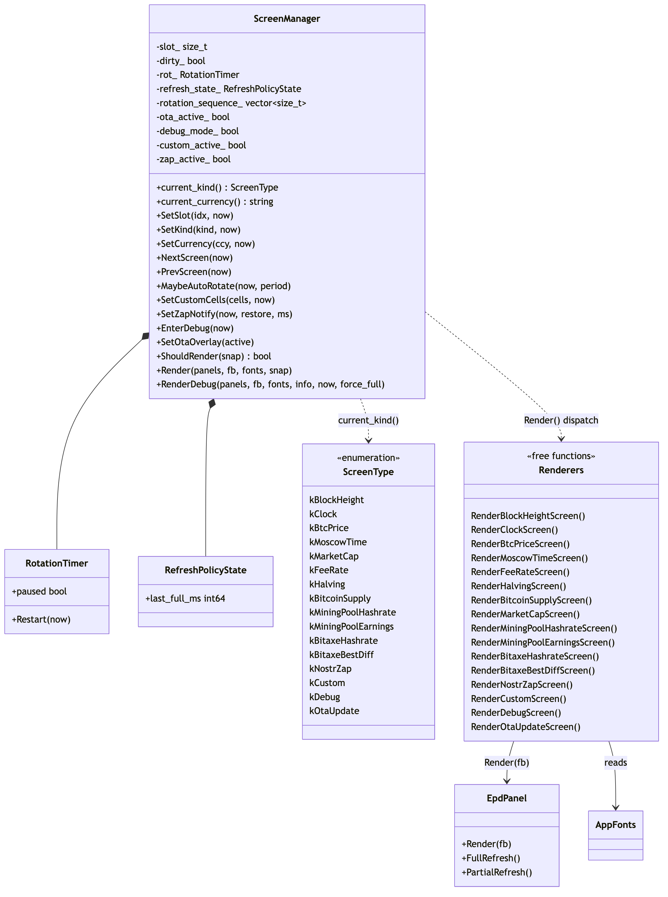
5. ScreenManager + renderers (class diagram)
ScreenManager (main/app/screen_manager.hpp:51)
owns the slot index, refresh policy, rotation timer, and last-rendered
diff state. Renderers are free template functions in
main/screens/ — there is no Screen base class.
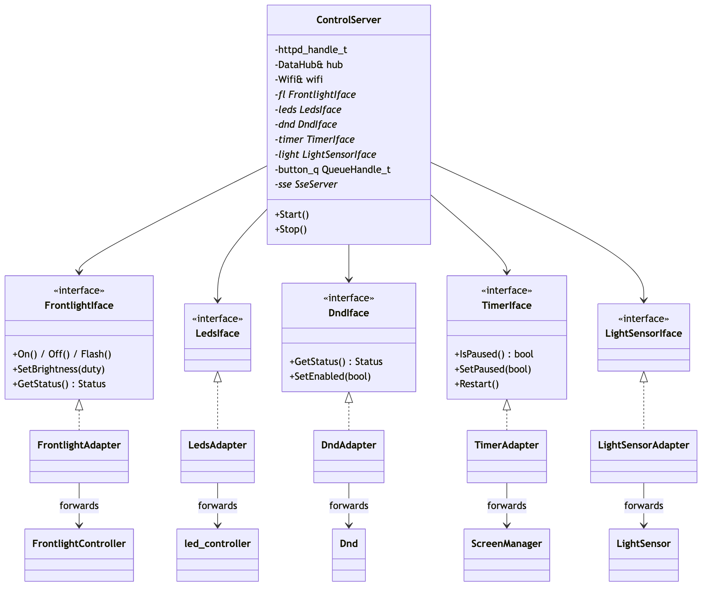
6. ControlServer + adapter interfaces (class diagram)
ControlServer (components/webserver/include/control_server.hpp)
talks to main/ only through pure-virtual *Iface interfaces so the
webserver component never has to include main/. main.cpp instantiates
adapter structs in main/app/boot/adapters.hpp
that forward to the real subsystems.
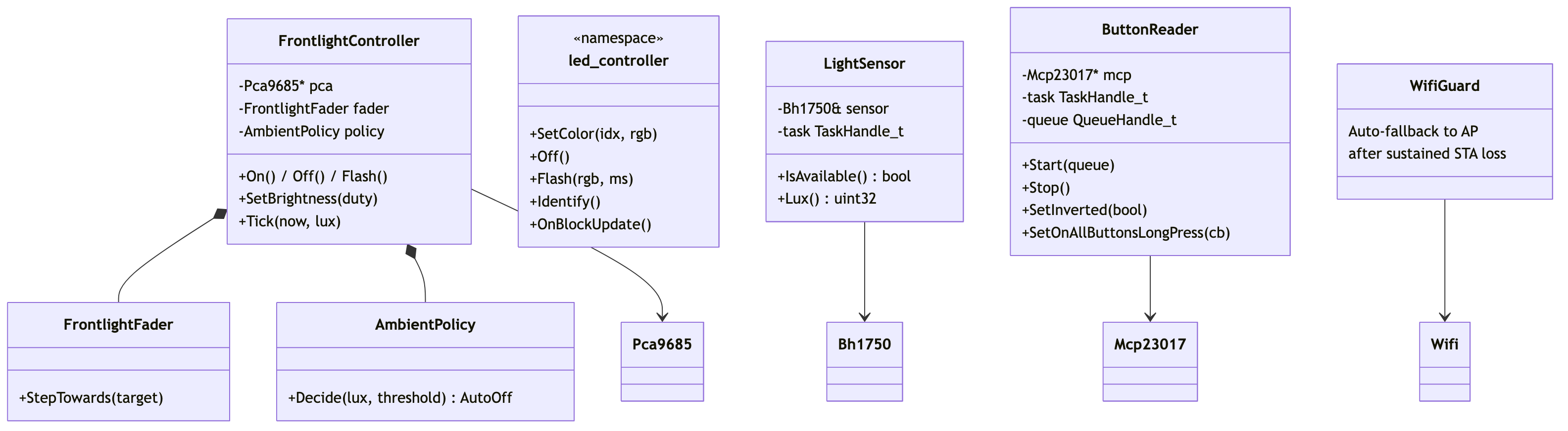
7. IO controllers (class diagram)
main/io/ wraps the chip drivers in higher-level controllers the rest of the app talks to.
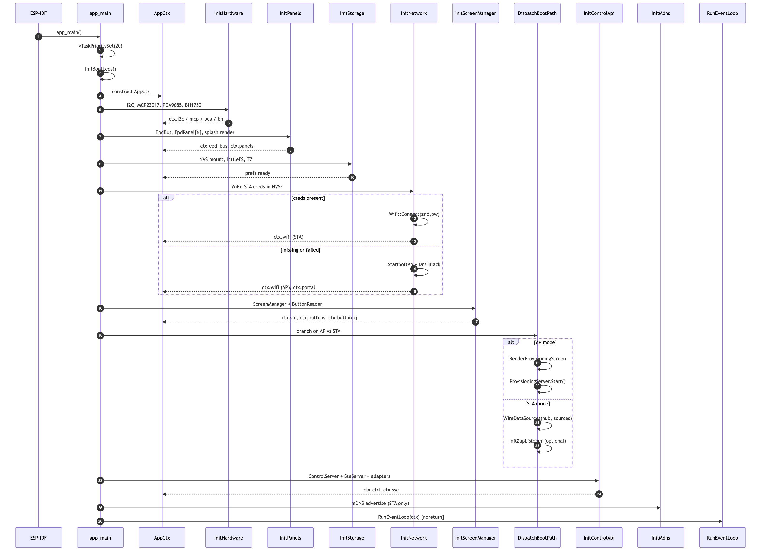
8. Boot sequence
app_main (main/main.cpp:37) is straight-line
wire-up. Each step populates AppCtx; the last call hands off to the
event loop.
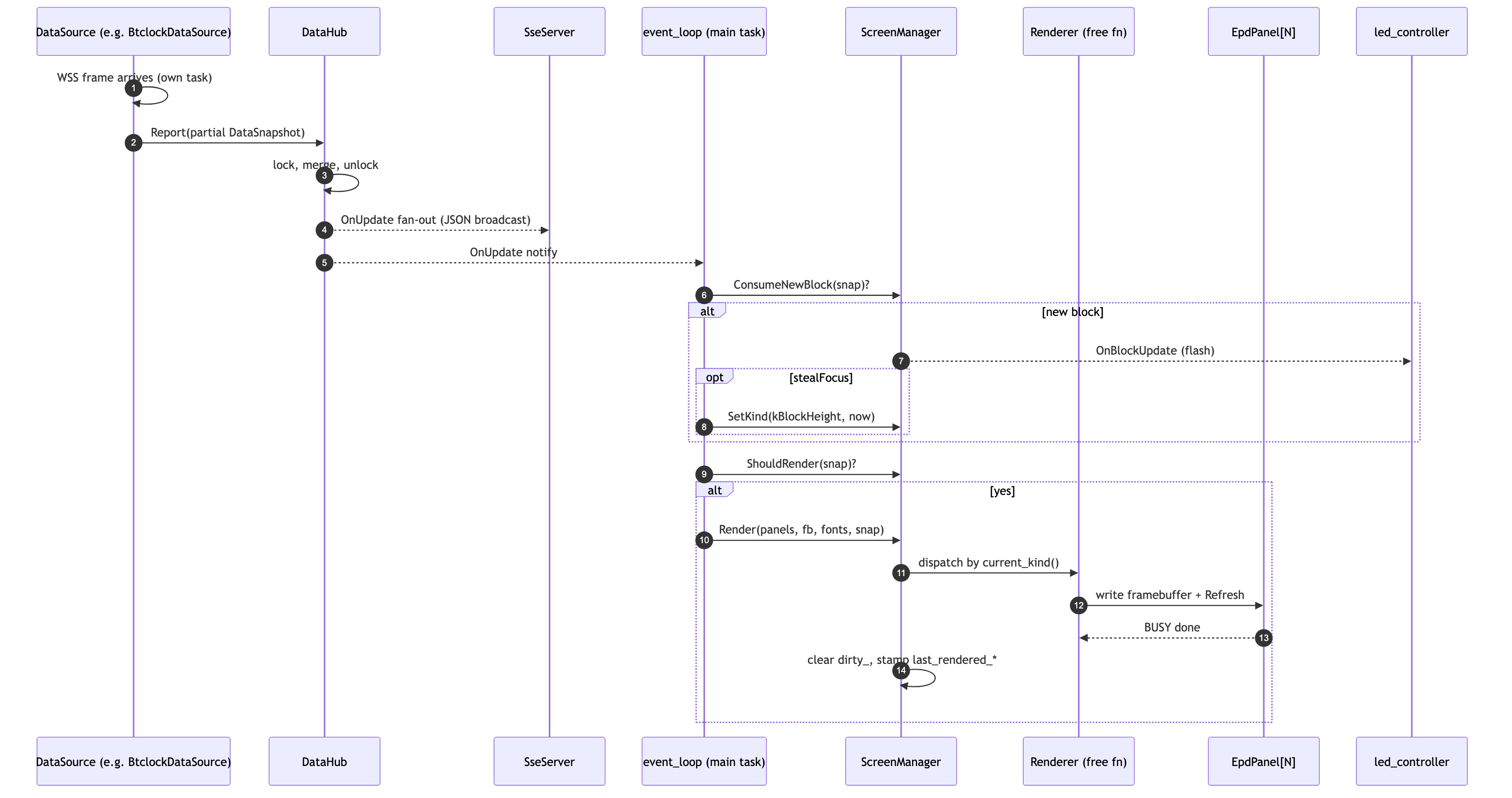
9. Data update → render
Hot path from a data source receiving a frame to pixels on the EPD.
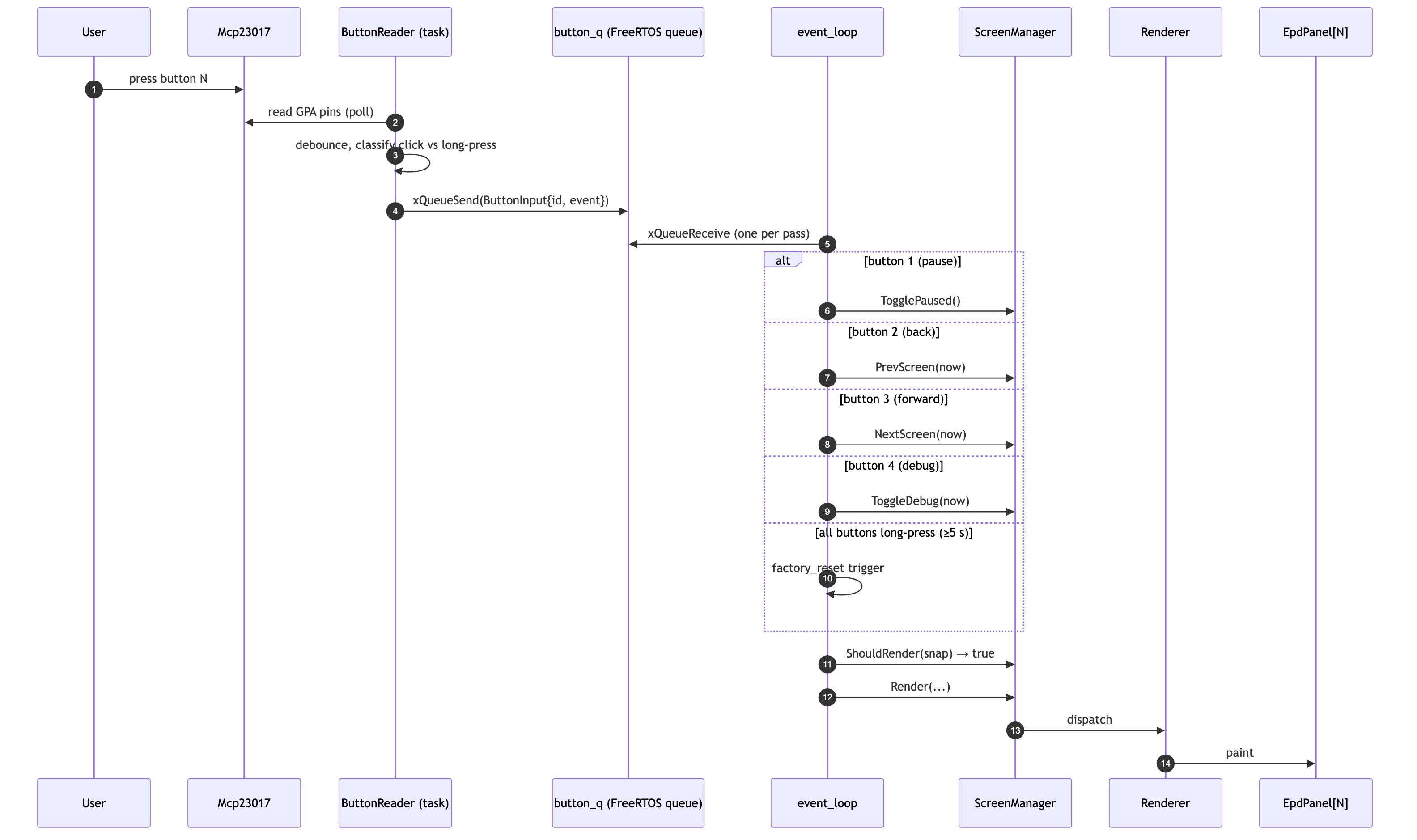
10. Button press → screen change
Buttons live on an MCP23017; the reader polls in its own task and drops events into a queue the main task drains.
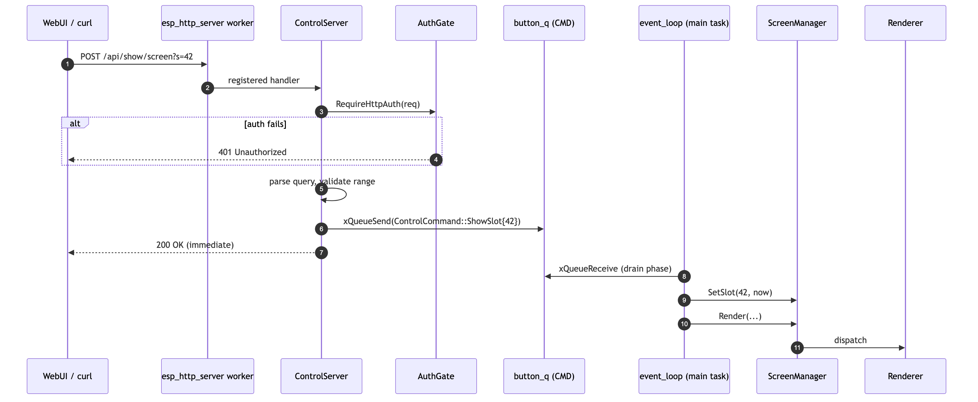
11. HTTP API → screen change
A WebUI / curl client jumps to a specific slot via
POST /api/show/screen?s=<idx>. Handlers run on the httpd worker task;
state mutation is queued for the main task to keep ScreenManager
single-threaded.
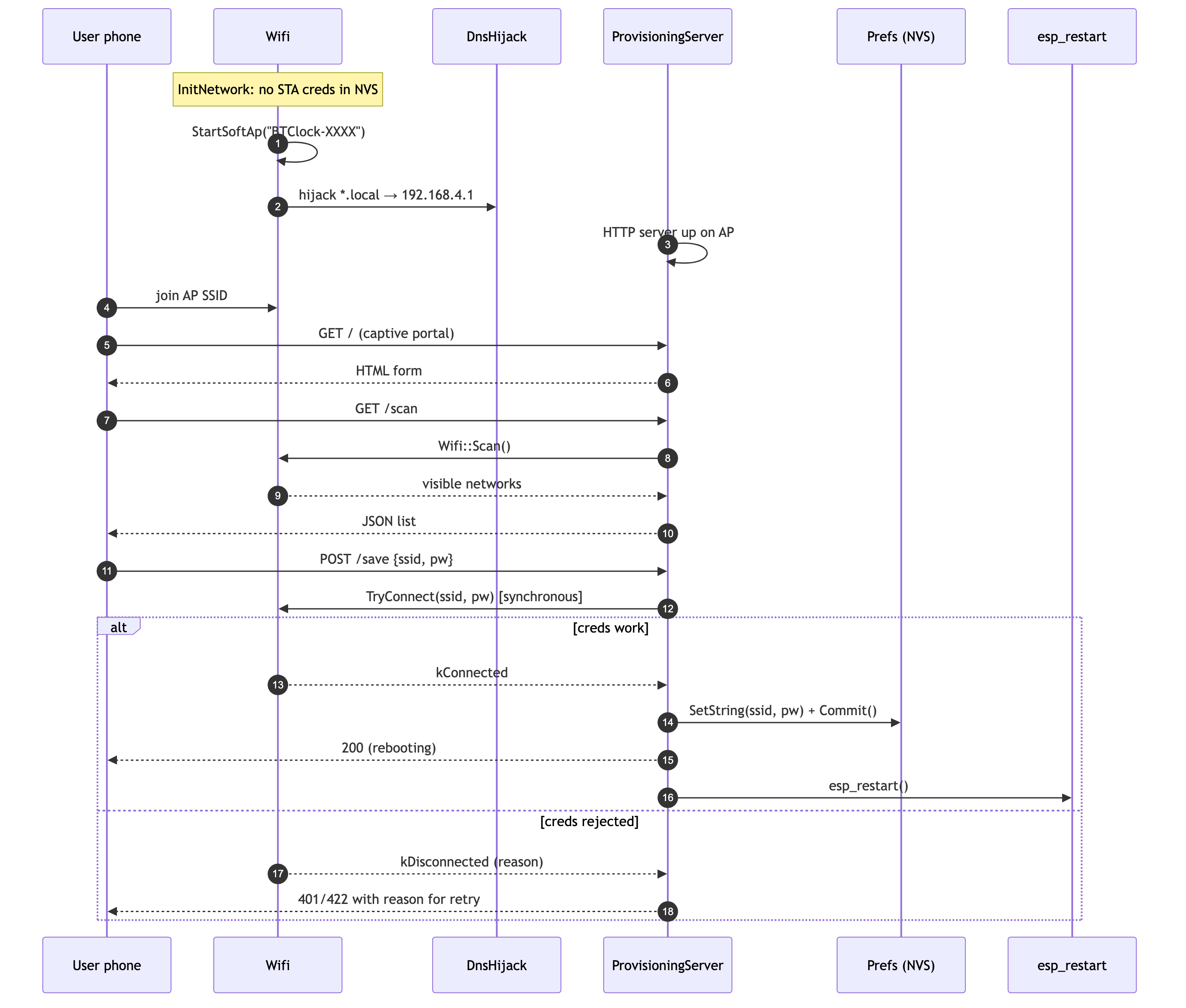
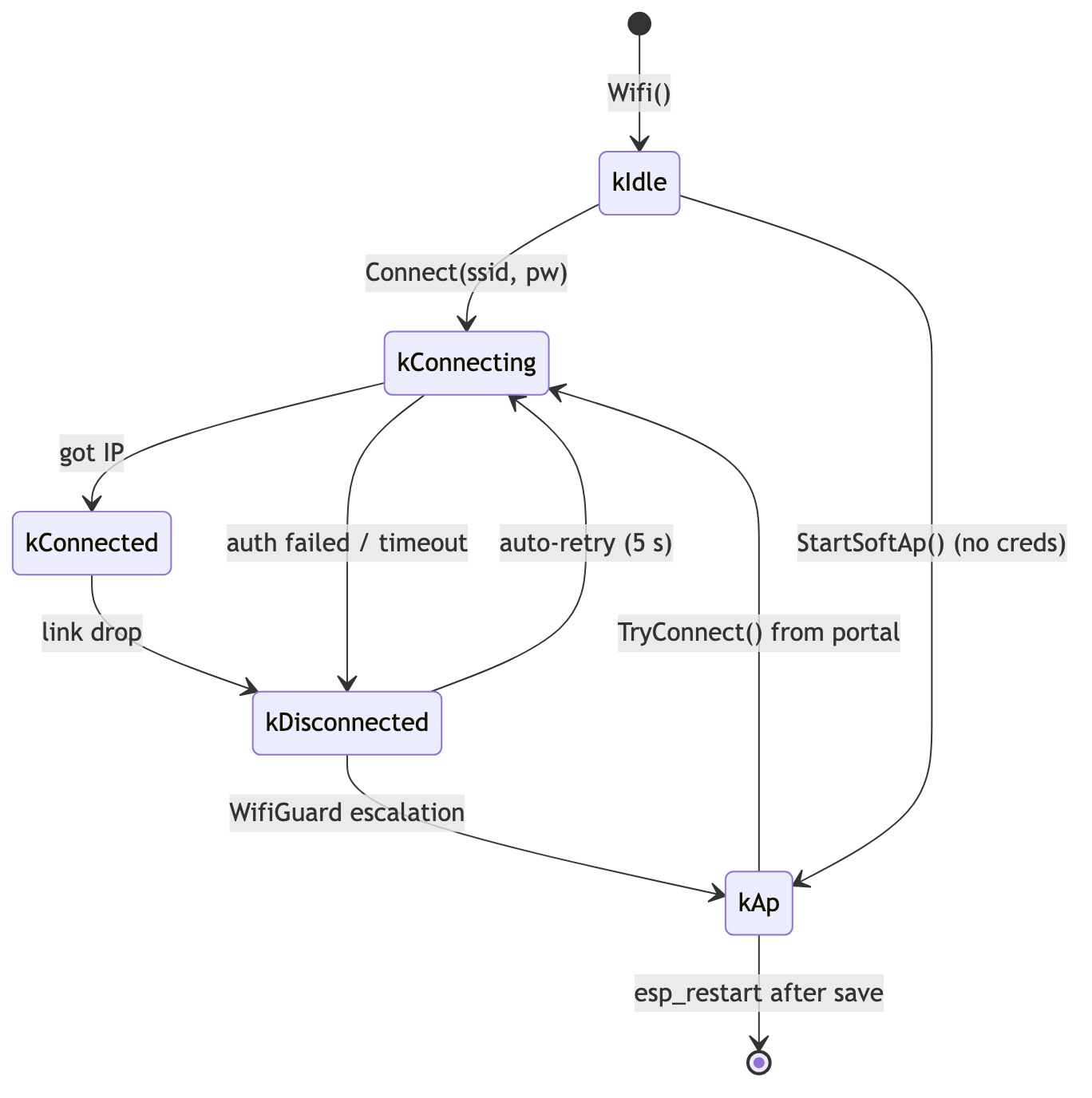
12. WiFi provisioning (AP → STA)
Cold-boot path when no STA credentials are stored: device puts up a SoftAP, the user joins it, the captive portal collects the new SSID/PSK, the device retries against STA, and on success persists creds and restarts.
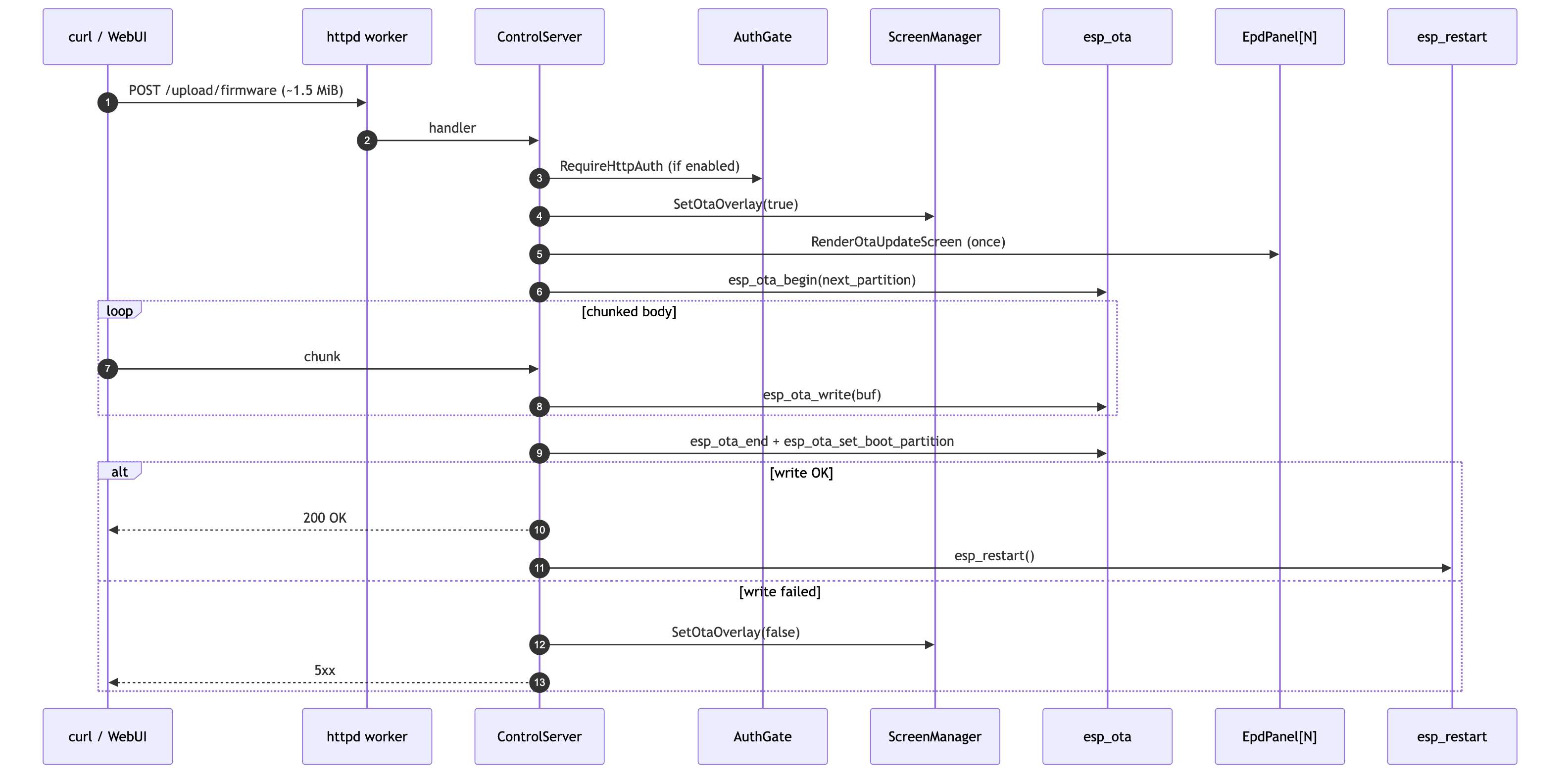
13. OTA firmware upload
POST /upload/firmware streams the new app partition. The handler
latches the OTA overlay on ScreenManager so the EPD shows progress
and the main loop stays out of the renderer for the duration.
14. WiFi state machine
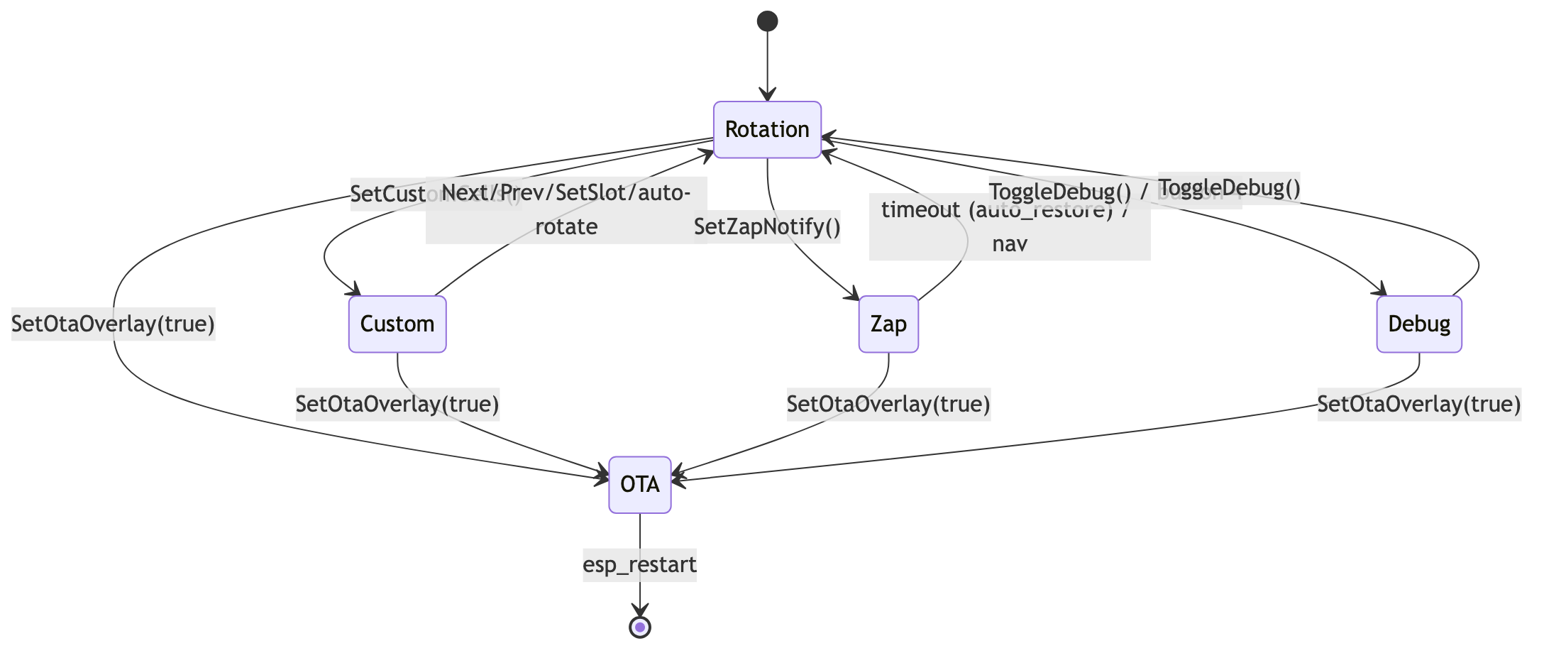
15. ScreenManager mode/overlay priority
ScreenManager has several latching overlays. Priority (highest first):
OTA > Debug > Zap notify > Custom > rotation slot.
16. Flash partition layout
The three partitions_*.csv files (partitions_4mb.csv,
partitions_8mb.csv, partitions_16mb.csv) carve flash into the
same six regions across every variant — only the sizes differ. NVS
sits at the conventional 0x9000 offset; both OTA app slots are
64 KiB-aligned so MMU-page mapping is clean; LittleFS holds the WebUI
bundle; the coredump partition catches panic backtraces. On Rev A the
coredump partition exists but capture is disabled at the sdkconfig
level (CONFIG_ESP_COREDUMP_ENABLE_TO_FLASH=n in
sdkconfig.defaults.rev_a) — the 4 MB
flash leaves the app partition with only ~3% headroom and the
~14 KiB capture path eats most of it. Rev B and V8 keep capture on
and serve the dump over GET /api/coredump.
| Partition | Type / subtype | Rev A (4 MB) | Rev B (8 MB) | V8 (16 MB) | Notes |
|---|---|---|---|---|---|
nvs |
data / nvs | 0x9000, 20 KiB |
0x9000, 20 KiB |
0x9000, 20 KiB |
Settings + WiFi creds + Nostr keys + LED prefs |
otadata |
data / ota | 0xe000, 8 KiB |
0xe000, 8 KiB |
0xe000, 8 KiB |
Boot-slot pointer for app_update |
app0 |
app / ota_0 | 0x10000, 1.6875 MiB |
0x10000, 3.4375 MiB |
0x10000, 6.9375 MiB |
Active firmware (per OTA) |
app1 |
app / ota_1 | 0x1C0000, 1.6875 MiB |
0x380000, 3.4375 MiB |
0x700000, 6.9375 MiB |
OTA staging slot |
storage |
data / littlefs | 0x370000, 412 KiB |
0x6F0000, 820 KiB |
0xDF0000, 2 MiB |
WebUI bundle + per-pool logo cache |
coredump |
data / coredump | 0x3D7000, 64 KiB (unused) |
0x7BD000, 64 KiB |
0xFF0000, 64 KiB |
ELF panic dump; pull via GET /api/coredump, clear via DELETE /api/coredump |
| unused tail | — | 0x3E7000, ~100 KiB |
0x7CD000, ~200 KiB |
— | Reserved for future partition growth without re-flashing the table |
Flash sizes are 4 MiB on Rev A (Lolin S3 Mini, no PSRAM constraint
beyond the chip's 2 MiB), 8 MiB on Rev B (ESP32-S3-WROOM-1-N8R2,
2 MiB PSRAM), and 16 MiB on V8 (8 MiB PSRAM). The OTA-able image
(btclock_v4.bin) lives in whichever app slot otadata points to;
/upload/firmware and the auto-update path
(components/ota/) write to the inactive slot,
flip otadata, and reboot.
File index
- Boot: main/main.cpp, main/app/boot/
- Runtime: main/app/event_loop.cpp, main/app/screen_manager.hpp
- Data: components/data_core/, main/sources/
- Pools: components/mining_pool_common/, components/mining_pool_*/
- HTTP: components/webserver/
- IO: main/io/
- Network: components/wifi/
- Settings: components/settings/, components/prefs/